The Limit Stop: The Safety Bumper
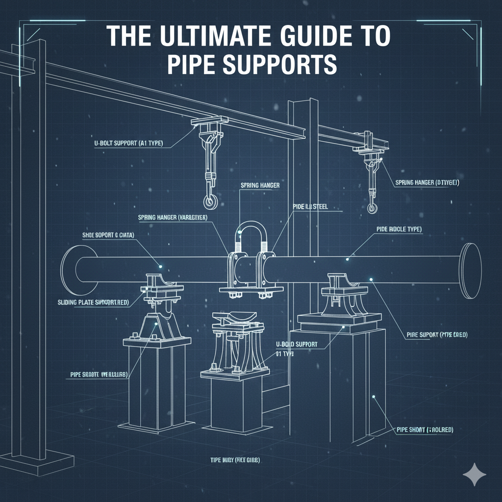
Pipe Supports
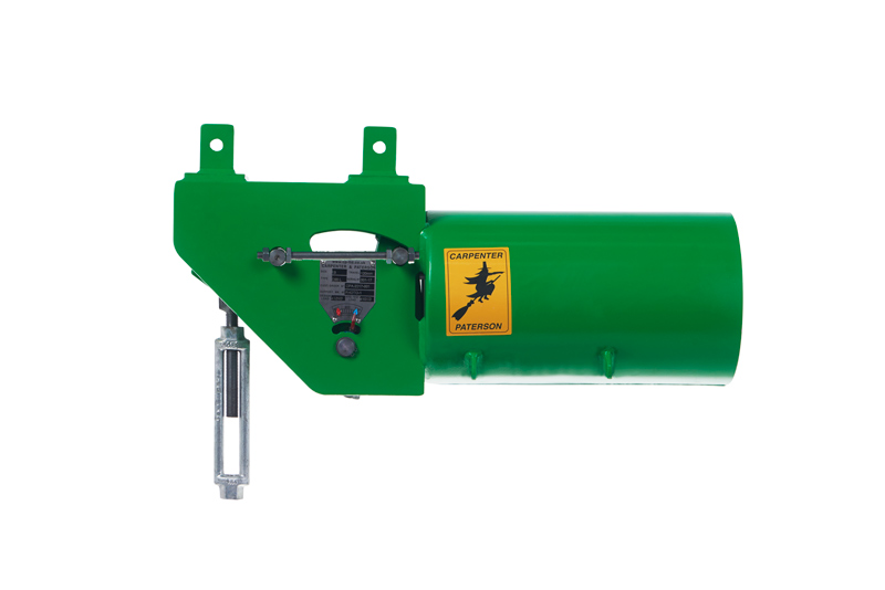
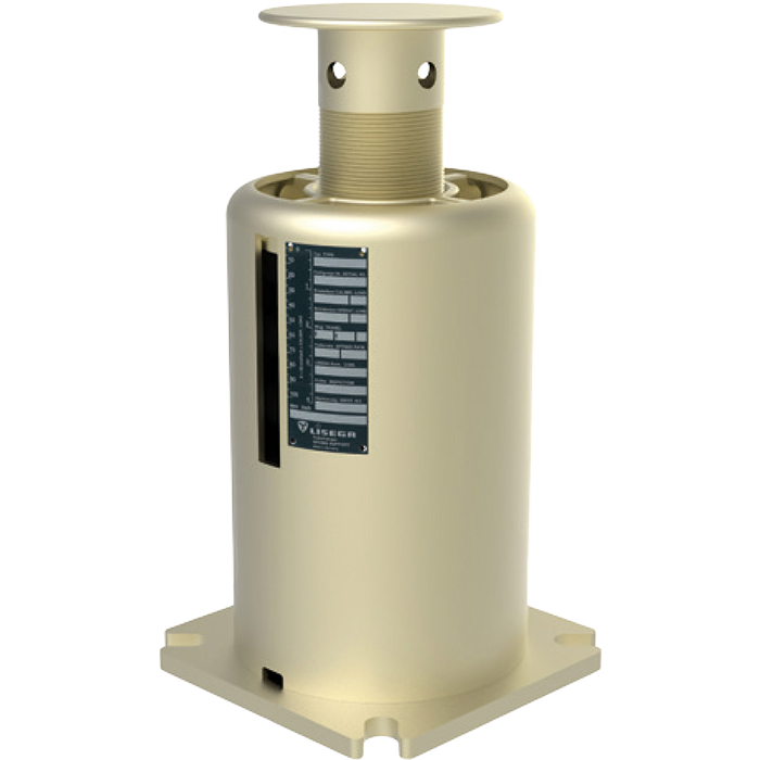

1. Definition & Function Deep Dive
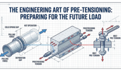
A limit stop (or “travel stop”) is a hybrid. It acts like a guide (allowing free movement) for a set distance, and then becomes an anchor (stopping movement), in a certain direction(s), once that distance is traveled.
2. Critical Application: Nozzle Protection
These are frequently used near sensitive rotating equipment like compressors or turbines. The piping engineer calculates that the equipment nozzle can only handle, for example, 1/4″ of thermal growth pushing against it. A limit stop is installed with exactly a 1/4″ gap. The pipe expands freely for that 1/4″, and then hits the “bumper,” transmitting any further thermal load into the support structure rather than the expensive compressor casing.
3. Installation Precision is Paramount
Limit stops require incredibly precise installation. If the design calls for a 1/4″ gap in the “cold” condition, and the installer sets it to 1/2″, the equipment nozzle may be overloaded before the stop even engages. Conversely, if set to 1/8″, the stop engages too early, generating unexpected stresses in the piping system. These must be field-verified with feeler gauges during construction.
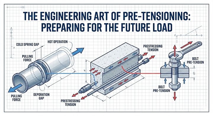
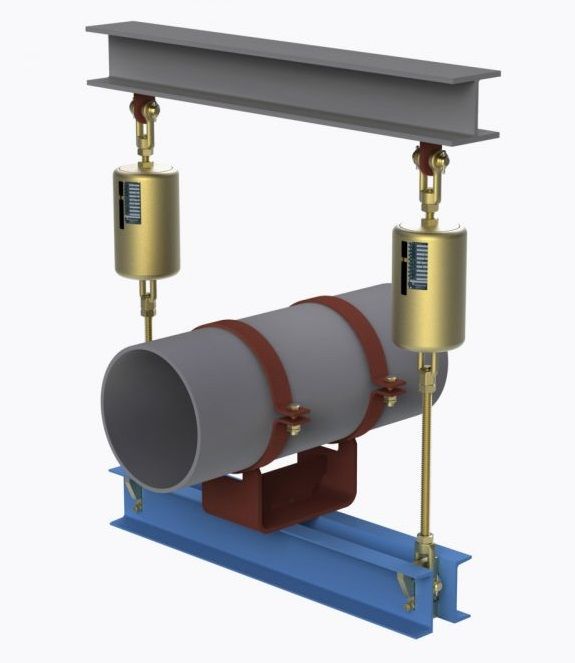
4. Load Transfer
In a Limit Stop (or travel stop) pipe support, load transfer occurs in two distinct phases based on the pipe’s movement:
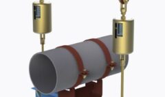
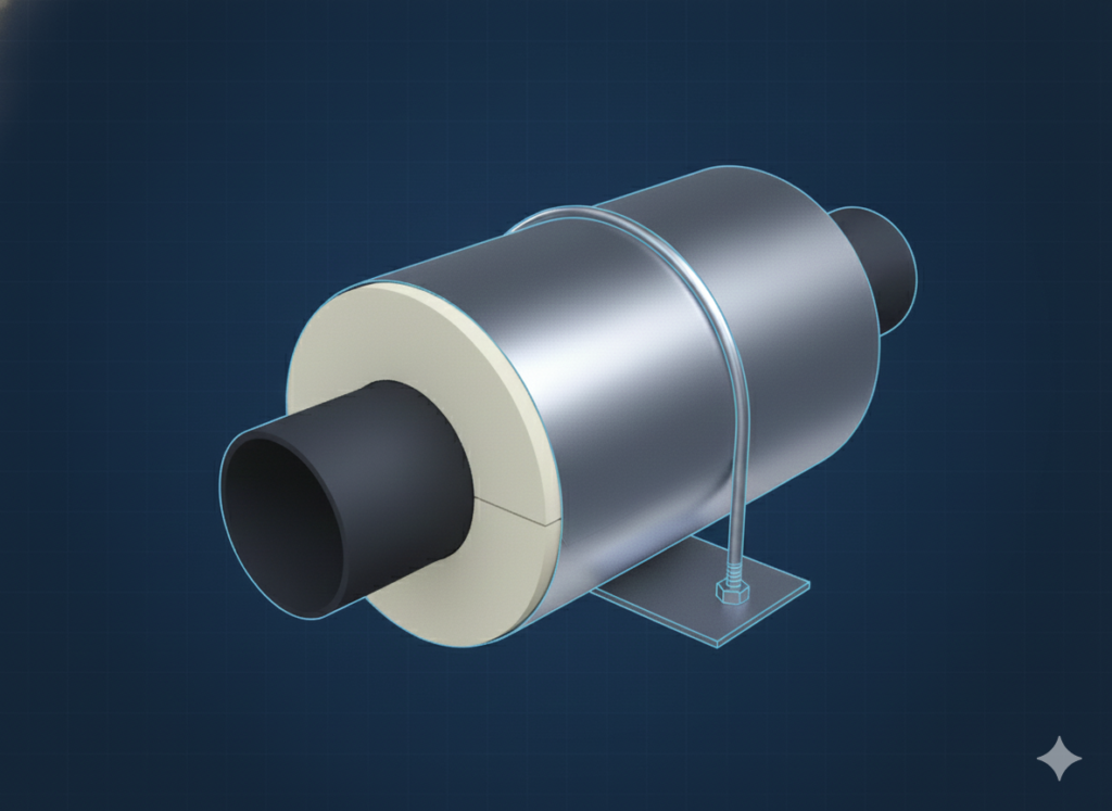
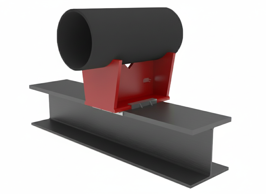
Free Expansion Phase (No Axial Load Transfer): Initially, the limit stop is installed with a pre-calculated gap or clearance between the pipe’s attachment (like welded lugs or a shoe) and the fixed stop surface on the supporting structure. During this phase, as the pipe heats up and expands, it moves axially within this gap. The support acts only as a guide, allowing free movement, and no axial thermal load is transferred to the support structure. The support may still carry the dead weight of the pipe if it’s designed as a resting support.
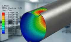
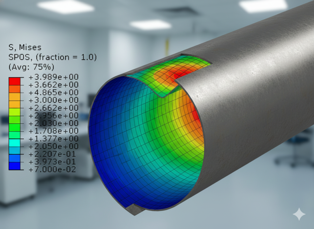
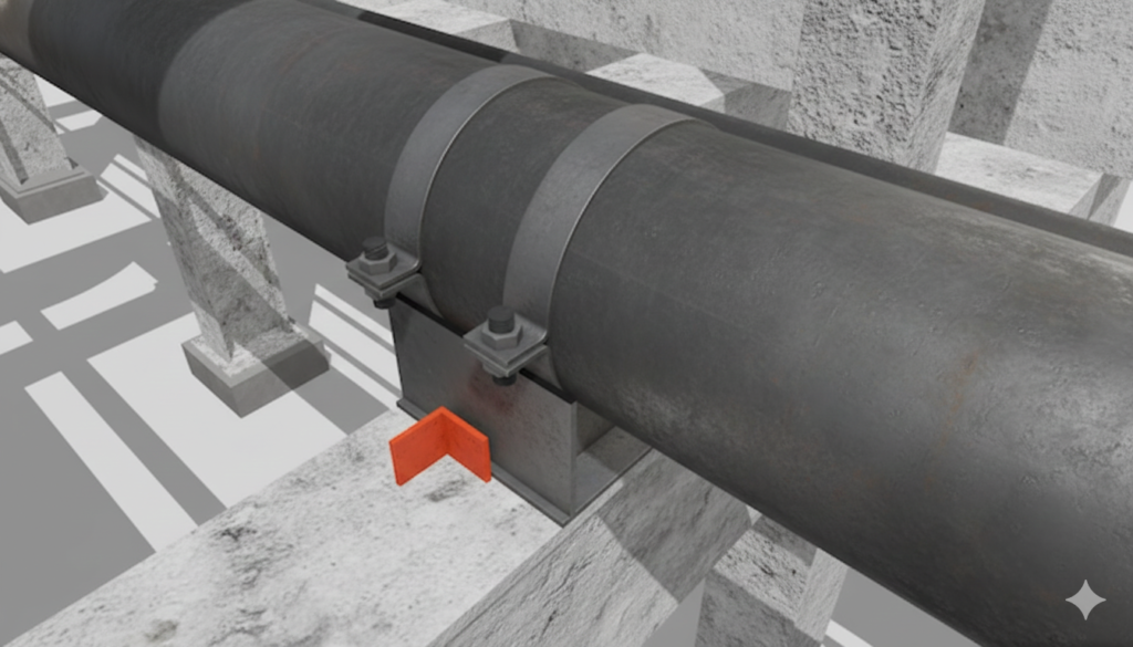
Engagement and Load Transfer Phase: Once the pipe’s expansion equals the pre-set gap distance, the pipe’s attachment makes physical contact with the fixed stop. At this precise moment, the support’s function changes from a guide to a rigid anchor. Any further tendency for the pipe to expand creates a tremendous thermal thrust force. Instead of moving the pipe further, this force is now transferred directly from the pipe wall, through its attachment lugs, into the limit stop’s structural frame, and finally into the main supporting beam or foundation. This effectively prevents any further movement in that direction, protecting downstream equipment (like pumps or vessels) from being subjected to excessive displacement and loads.