Piping Isometrics: The Blueprint for Fabrication and Construction 📝
0 comments
Piping Isometrics: The Blueprint for Fabrication and Construction 📝
- Introduction: What is a piping isometric drawing? Its unique 3D representation on a 2D plane. Why it's indispensable for fabrication and installation.
- Purpose and Importance of Isometrics:
- Provides all necessary information for a specific pipe spool to be fabricated and installed.
- Acts as a communication tool between design, fabrication shop, and field construction team.
- Used for material take-off (MTO) verification, weld tracking, NDE mapping, pressure test planning.
- Information Conveyed on a Piping Isometric:
- Line Number and Specifications: Identifies the pipe, its material, size, operating conditions.
- Dimensions and Routing: Clear depiction of pipe lengths, angles, changes in direction. North arrow for orientation.
- Bill of Materials (BOM): Lists all components (pipes, fittings, flanges, valves, gaskets, bolts) with quantities, sizes, material grades.
- Weld Information: Location and type of welds (shop vs. field welds), weld numbers.
- Support Locations and Types (sometimes shown, or referenced).
- Insulation and Tracing Details.
- Slope and Flow Direction.
- Connection Details: To equipment nozzles, other pipes (coordinates, flange ratings).
- Reference Drawings: P&ID, General Arrangement (GA) drawings.
- NDE Requirements.
- Pressure Test Data.
- How to Read and Interpret Piping Isometrics:
- Understanding isometric projection (30/30 degree axes).
- Recognizing symbols for fittings, valves, welds.
- Following continuations to other isometric drawings.
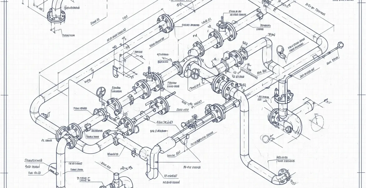
- Creation of Isometrics:
- Historically: Manual drafting.
- Currently: Primarily extracted from 3D plant design models (e.g., PDMS, S3D, Plant 3D), ensuring consistency and accuracy.
- Role in Pre-Fabrication and Field Installation:
- Shop Fabrication: Spools are cut, bent, welded in a controlled environment based on the isometric.
- Field Erection: Guides installers on how to connect spools and components.

- Checking Isometrics for Accuracy and Completeness: A critical QA/QC step. Verifying dimensions, materials, orientations, BOM against P&IDs and 3D model.
- ASME Code Relevance: While an isometric is a drawing, the design it represents must comply with ASME B31.3 (e.g., component selection, pressure design, flexibility). Fabrication and examination details on the iso reflect requirements from codes like ASME B31.3 Chapter V (Fabrication, Assembly, Erection) and Chapter VI (Inspection, Examination, Testing). Welding symbols often follow AWS standards.
- Conclusion & Call to Action: Piping isometrics are the workhorses of piping construction. The ability to accurately create, read, and check them is a fundamental skill. Training courses focused on drafting standards, isometric interpretation, and the use of 3D modeling software for isometric extraction are vital for designers, fabricators, and construction personnel to ensure pipes are built as designed and meet all project and code requirements.
Related Posts
Selecting the Right Pipe Supports: Types, Functions, and Design Considerations 🛠️
August 13, 2025
37 views
Fundamentals of Pipe Routing: Best Practices for Efficient and Safe Layouts 📐
August 11, 2025
67 views
The Piping Engineer’s Toolkit: Essential Software and Resources 💻
August 3, 2025
84 views
Ensuring Safety in Piping Systems: Design and Operational Considerations 🛡️
July 27, 2025
58 views
Piping Project Management: From Concept to Completion 🏁
July 16, 2025
59 views
Search
Categories
Popular Tags