The Indispensable Language of Piping Engineering: Understanding the P&ID

piping alphabets
Piping Design Piping Engineering

The Indispensable Language of Piping Engineering: Understanding the P&ID

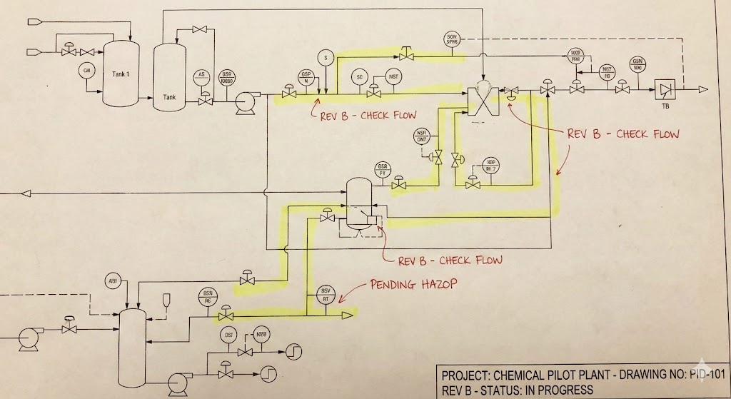
In the complex world of piping engineering and design, clarity and precision are paramount. The Piping and Instrument Diagram (P&ID), which is often referred to as the Mechanical flow diagram, serves as the foundational document for project execution. It is commonly called the “bible” of the design process, providing specific and necessary design criteria to the pipe drafter.

The P&ID as the Definitive Blueprint

The importance of the P&ID stems from the level of detail it captures, which far surpasses that of the preliminary Process flow diagram. This document dictates the exact sequence in which all mechanical equipment, valves, instrumentation, and connections must be implemented for every process pipe routed through the facility.

A comprehensive P&ID must define:

  1. Pipe line numbers and the direction of the commodity flow.
  2.  Pipe specifications and line sizes.
  3. All mechanical equipment.
  4. All operating and isolating valves.
  5. All controlling instrumentation along with their transmitting devices.

Guiding Design and Execution

The P&ID provides structure and guidance throughout the project lifecycle:

  1. Layout and Routing: The piping group utilizes the flow diagram (P&ID) when developing and laying out the plot plan. Subsequently, the piping designer routes the pipe configurations according to the P&ID, ensuring adherence to accepted design practices and project specifications.
  2. Tracking Progress: As each pipe line is fully designed and incorporated into the project, the flow diagram is typically “yellowed out”
  3. Schematic Visualization: P&IDs are schematic drawings, meaning they are not drawn to scale. They guide the designer by conveying flow logic and arrangement, usually laid out in a simplistic order to be “read” from left to right. For instance, all valves, regardless of their actual pipe size or pound rating, are typically drawn the same size on flow diagrams
  4. Final Approval: The P&ID is a dynamic document that may undergo revisions throughout the design phase. Critically, once finalized, flow diagrams must be stamped for “release” by a registered professional engineer before they can be approved for construction.
Piping and Instrumentation diagram with Progress

The Symbolic Language of Instrumentation

A key component of the P&ID language is the intricate system used to identify and communicate instrumentation necessary for the safe and efficient operation of the facility. Instruments must monitor, adjust, and regulate commodity levels, temperatures, pressures, and flow.

P&IDs achieve this through a specialized symbolic language based on combinations of groups and types:

Four Basic Instrument Groups: Flow (F), Level (L), Pressure (P), and Temperature (T).

Five Specific Instrument Types: Controller (C), Indicator (I), Gauge (G), Alarm (A), and Recorder (R).

By learning the combination of these nine terms, one can interpret most instrumentation symbols found on a P&ID. The first letter in the instrument symbol typically denotes the instrument group, while the subsequent letters indicate the type (e.g., PI for Pressure Indicator).

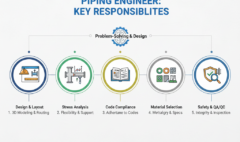
For anyone working on piping projects, whether as drafters, designers, or engineers, mastering the specific symbols, abbreviations, and conventions found in P&IDs is imperative to interpret the documents correctly and ensure smooth project coordination

Leave your thought here

Your email address will not be published. Required fields are marked *

Select your currency
Select the fields to be shown. Others will be hidden. Drag and drop to rearrange the order.
  • Image
  • SKU
  • Rating
  • Price
  • Stock
  • Availability
  • Add to cart
  • Description
  • Content
  • Weight
  • Dimensions
  • Additional information
Click outside to hide the comparison bar
Compare