Inside the Claus Process: How Sulfur Recovery Units Keep Refineries and Gas Plants Compliant
Inside the Claus Process: How Sulfur Recovery Units Keep Refineries and Gas Plants Compliant
Industrial Powerhouse: Sulfur in Modern Applications



2.0 Introduction: From Waste Gas to Valuable Product
Every refinery and gas plant that processes sour feedstock eventually faces the same engineering problem: what to do with the hydrogen sulfide stripped out during treating. The answer, for the better part of a century, has been the same — convert it into elemental sulfur through what is now called the Claus process, named after the German chemist who patented the underlying reaction in 1883.
What looks like a single conversion step on a process flow diagram is, in practice, one of the more demanding pieces of equipment in a modern facility to design, operate, and maintain. Sulfur recovery units (SRUs) combine high-temperature combustion, multi-stage catalytic conversion, and corrosive process chemistry in a compact footprint, often with regulatory emissions targets above 99.9% recovery efficiency. This post — Part 2 of our sulfur series — walks through how the Claus process works and the specific mechanical, piping, and materials decisions that separate a reliable SRU from a maintenance headache.
2.1 The Role of Sulfur Recovery Units in Refining & Gas Processing
2.1.1 Regulatory Drivers
Sulfur recovery exists because emitting H2S or burning it uncontrolled into SO2 is not permitted under modern air quality regulations in virtually any jurisdiction. Permits typically specify minimum recovery efficiencies, and facilities that fall short face both compliance penalties and reputational exposure. This regulatory pressure has only intensified as fuel sulfur specifications have tightened over the past two decades, pushing more sulfur load through SRUs that were often sized for an earlier, less stringent era.
2.1.2 SRU Placement in the Process Flow
Sour gas leaving an amine treating unit carries concentrated H2S, which routes directly to the SRU. The recovered elemental sulfur typically exits as a liquid, is degassed to remove residual H2S, and is either stored molten or solidified for shipment. The SRU’s tail gas — what remains after sulfur recovery — usually passes through a tail gas treatment unit before final incineration, since even a small percentage of unconverted sulfur compounds can represent a significant emissions volume on a large facility.
2.2 The Claus Process Explained
2.2.1 Thermal Stage Reactions
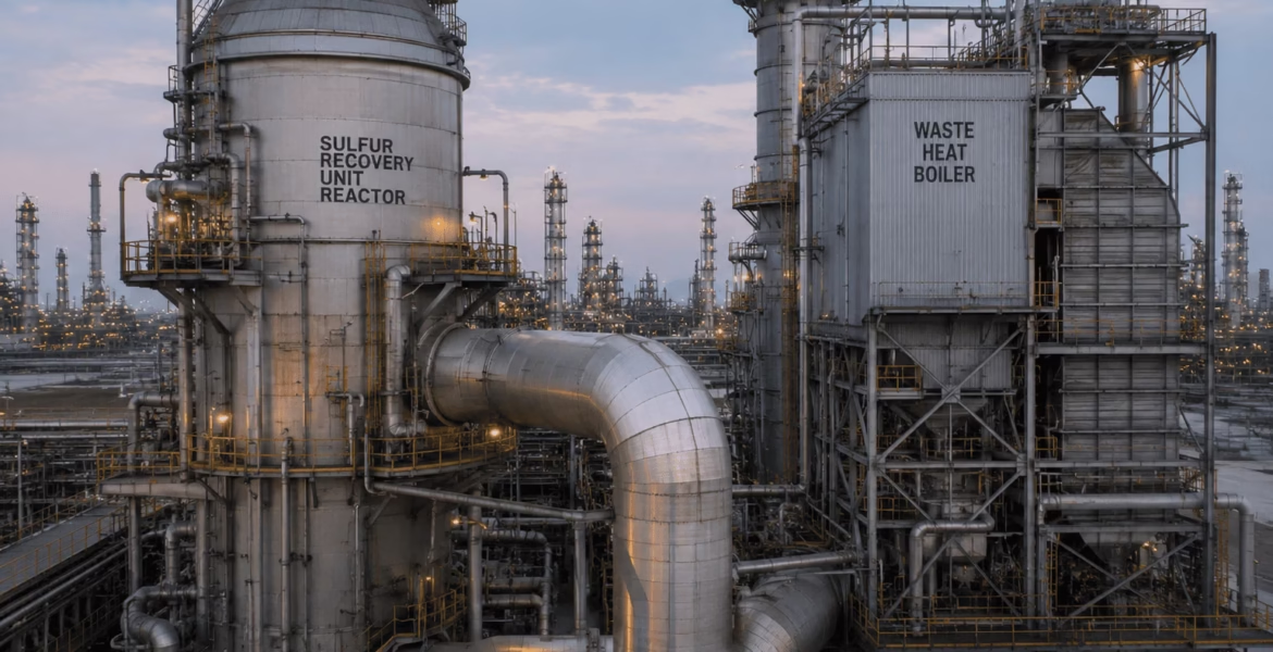
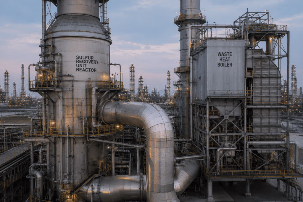
The first stage burns roughly one-third of the incoming H2S with a controlled, sub-stoichiometric air supply in a reaction furnace, generating sulfur dioxide and significant heat. This thermal stage typically converts 60–70% of the available sulfur and operates at temperatures that can exceed 1,000°C, placing extreme demands on furnace refractory and waste-heat-boiler design.
2.2.2 Catalytic Stage and Conversion Efficiency
The partially converted gas then passes through two or three catalytic reactor stages, each using alumina or titania-based catalyst beds to drive the remaining H2S and SO2 toward elemental sulfur at progressively lower temperatures. Each stage includes a condenser to recover liquid sulfur before the gas proceeds to the next bed, since pushing conversion further requires cooling the equilibrium-limited reaction.
2.2.3 Tail Gas Treatment Units
Because the Claus reaction is equilibrium-limited, even a well-run three-stage unit typically recovers only 95–97% of incoming sulfur. To meet modern regulatory thresholds above 99.9%, facilities add a tail gas treatment unit (TGTU), which hydrogenates remaining sulfur species back to H2S and recycles it to the amine system — effectively closing the loop on sulfur recovery.
2.3 Mechanical & Piping Design Considerations for SRUs
2.3.1 High-Temperature Piping and Equipment Design
The reaction furnace and waste heat boiler interface represents one of the most thermally severe boundaries in the entire facility, requiring careful attention to thermal expansion, refractory-lined piping, and support design that accommodates large temperature swings during startup and shutdown. Piping engineers working SRU revamps frequently cite flexibility analysis around this interface as one of the more complex stress problems they encounter, since both thermal growth and external nozzle loads from rotating and static equipment must be reconciled simultaneously.
2.3.2 Material Selection for Sulfur-Bearing Streams
Liquid sulfur piping and storage systems require materials and design details that account for sulfur’s tendency to solidify and plug lines if temperature control is lost — most facilities use steam or hot-oil tracing on all molten sulfur piping for this reason. Elsewhere in the unit, condensers and reactor internals must resist both high-temperature sulfidation attack and the corrosive combination of moisture and SO2/H2S during shutdown periods, when condensation chemistry becomes far more aggressive than during steady-state operation.
2.3.3 Pressure Relief and Safety Systems
Given the toxicity of H2S and the exothermic nature of the Claus reactions, SRUs require carefully engineered pressure relief and emergency isolation systems, sized for credible overpressure scenarios including catalyst bed runaway and loss of cooling. Relief system design here is rarely a simple textbook exercise — multi-phase relief streams and the need to route discharges safely away from personnel both add complexity beyond standard relief valve sizing.
2.4 Common Operational Challenges
2.4.1 Catalyst Deactivation and Fouling
Claus catalyst beds gradually lose activity due to sulfation, carbon fouling, and exposure to contaminants like BTEX compounds carried over from upstream treating units. Operators typically plan catalyst replacement on a multi-year cycle, but poor upstream control can accelerate deactivation significantly, reducing recovery efficiency and risking permit excursions.
2.4.2 Corrosion and Refractory Degradation
Reaction furnace refractory experiences cyclic thermal stress with every startup and shutdown, and waste heat boiler tubes are vulnerable to both high-temperature sulfidation and acid dew-point corrosion during cooler operating periods. Inspection programs for SRUs typically combine periodic internal inspection with thickness monitoring at known high-risk locations identified through fitness-for-service assessment methodology.
2.5 Conclusion
Sulfur recovery units sit at an unusual intersection of combustion engineering, catalytic process design, and corrosive-service piping and pressure equipment — all under tight regulatory scrutiny. Reliable SRU performance depends as much on sound mechanical design and materials selection as it does on process chemistry, which is exactly the kind of cross-disciplinary challenge piping and mechanical engineers are increasingly expected to navigate.
Want to build deeper expertise in the piping and pressure equipment design challenges SRUs present? Explore our B31.3 Process Piping course, our Materials and Design for High Temperatures course, and our Pressure Relief Devices: Design, Sizing, Construction, Inspection and Maintenance course.
Recommended Training Courses
- B31.3 Process Piping
- Materials and Design for High Temperatures
- Pressure Relief Devices: Design, Sizing, Construction, Inspection and Maintenance
External References
2.6 FAQ
Q1: Why can’t the Claus process recover 100% of incoming sulfur?
The Claus reaction is thermodynamically equilibrium-limited, which caps single-train recovery around 95–97% even with multiple catalytic stages — hence the need for a tail gas treatment unit to reach modern regulatory thresholds.
Q2: Why is molten sulfur piping always heat-traced?
Elemental sulfur solidifies below roughly 115°C, so piping must be maintained above its melting point with steam or hot-oil tracing to prevent plugging.
Q3: What causes most SRU mechanical failures?
High-temperature sulfidation, refractory thermal cycling damage, and acid dew-point corrosion during shutdowns are among the most common root causes of SRU mechanical issues.
Q4: How often is Claus catalyst typically replaced?
Replacement intervals vary by feed quality and contaminant loading, but many facilities plan on a multi-year cycle, with performance monitoring used to detect early deactivation.
Q5: What standards typically govern SRU pressure equipment design?
SRU vessels and piping commonly fall under ASME Boiler and Pressure Vessel Code and ASME B31.3 process piping requirements, alongside API guidance for refining-specific equipment.